Tag: Raspberry PI
-
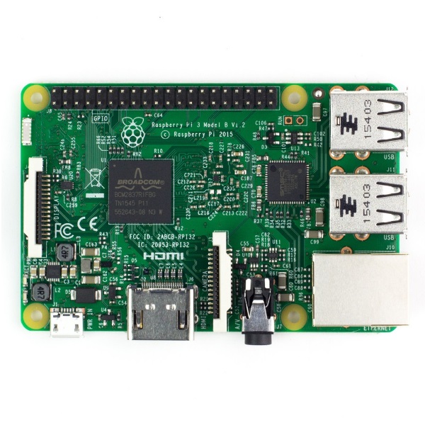
Raspberry PI 3 is here
Raspberry Pi 3 Model B Quad Core 1.2GHz 64bit CPU 1GB RAM WiFi & Bluetooth 4.0 Built on the latest Broadcom 2837 ARMv8 64bit processor, the new generation Raspberry Pi 3 Model B is faster and stronger than its predecessors. With built-in wireless and Bluetooth connectivity, it becomes the ideal IoT-ready solution. FEATURES: 1.2GHz QUAD…
-
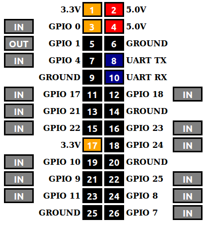
WebIOPi – Internet of Things framework
Control, debug, and use your Pi’s GPIO, sensors and converters from a web browser or any app WebIOPi is the perfect Swiss-knife to make connected things Developed and provided by Eric PTAK (trouch) Runs on Raspberry Pi Tutorials WebIOPi Community Forum Developer’s Blog (Eric/trouch) Links: Google Code: https://code.google.com/p/webiopi/ Blog: http://trouch.com/ Video of WebIOPi: https://www.youtube.com/watch?v=0i2C3Qagosc&feature=youtu.be
-
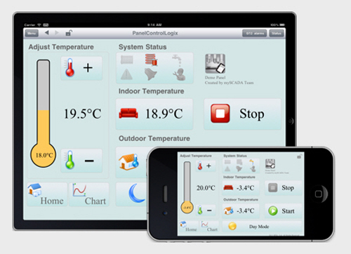
MyScada – supervisory control and data acquisition
SCADA (supervisory control and data acquisition) is a system operating with coded signals over communication channels so as to provide control of remote equipment (using typically one communication channel per remote station). The control system may be combined with a data acquisition system by adding the use of coded signals over communication channels to acquire…
-
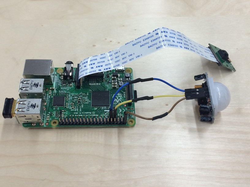
List of projects – Raspberry – Arduino
Robots related projects Navigation and Obstacles Avoidance The RR.O.P. – RaspRobot OpenCV Project Car Lab Obstacle detection using OpenCV Code on GitHub Autonomous bottle recycling robot Tracking and Recognition Basic motion detection and tracking with Python and OpenCV Raspberry Pi and the Camera Pi module: face recognition tutorial Tutorial: Using CamShift to Track Objects in…
-

Windows 10 – The Internet of your things
The Internet of Things (IoT) brings together devices, sensors, cloud, data and your imagination. Build what matters most to you. Rapidly prototype and build your Windows IoT solutions on a variety of devices running Windows 10 IoT Core. Windows 10 gives you powerful tools that let you develop fast and deploy to your device. https://dev.windows.com/en-us/iot…
-
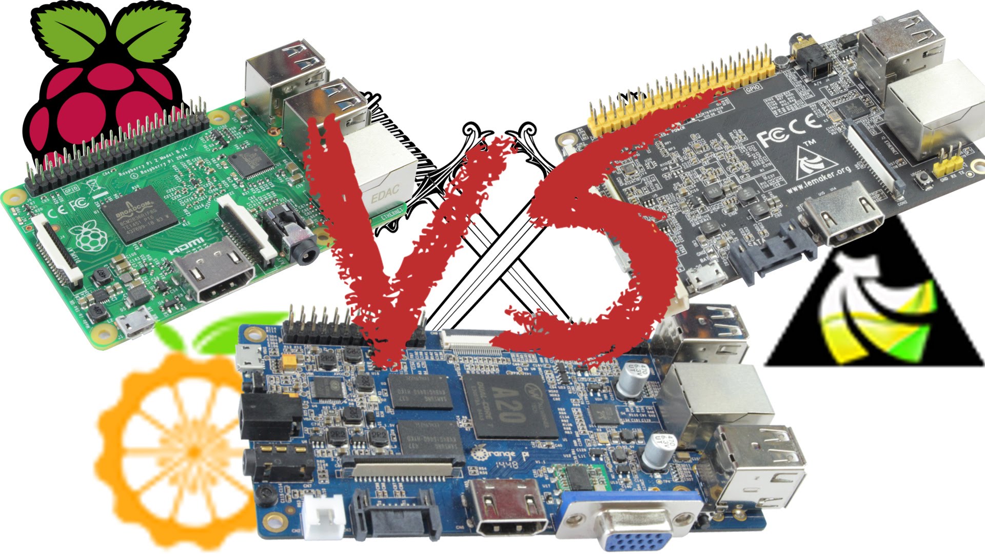
Raspberry Pi 2 VS Orange Pi VS Banana Pro
A great video of comparison between Banana Pi, Orange Pi and Raspberry Pi. Very interesting features: Wifi, Charging Battery, Power consumption etc… seems like Banana pi takes them all… More comparison links: http://socialcompare.com/en/comparison/raspberrypi-boards-look-alike-2spubijh http://www.htpcguides.com/raspberry-pi-vs-pi-2-vs-banana-pi-pro-benchmarks/
-

Banana Pi – A Highend Single-Board Computer
Banana Pi What is Banana Pi? http://www.bananapi.org/p/product.html Banana Pi is a single-board computer. Banana Pi targets to be a cheap, small and flexible enough computer for daily life. Built with ARM Cortex-A7 Dual-core CPU and Mali400MP2 GPU, and open source software, Banana Pi can serve as a platform to make lots of applications for different…